

Views: 0 Author: Site Editor Publish Time: 2026-10-13 Origin: Site


Imagine diagnosing a sudden engine misfire or a malfunctioning infotainment screen. You might spend hours chasing a ghost. Eventually, the root cause reveals itself as a single loose electrical wire hidden deep within the engine bay. In the automotive industry, failing electrical connections due to mismatched or low-quality housings frequently lead to costly warranty repairs, intermittent system failures, and compromised vehicle safety.
The automotive environment is notoriously unforgiving. Electrical systems endure extreme thermal cycling, relentless road vibrations, exposure to corrosive fluids, and high-pressure moisture. Under these grueling conditions, selecting the correct structural shell for your wiring becomes a critical engineering requirement for long-term vehicle reliability rather than a simple matter of convenience.
This guide serves as a practical blueprint for field engineers, mechanics, and harness builders. We will explore the core variables of connector selection—Pitch, Pin Count, Locking mechanisms, and Keying—to help you specify the perfect housing for both inline and board-level applications.
Pitch dictates the physical footprint and the voltage or current carrying capabilities of the connector.
Pin count must accommodate your immediate circuit requirements while factoring in physical space limits and future expansions.
Locking mechanisms like TPA and CPA are non-negotiable features for preventing accidental disconnections caused by engine harmonics.
Keying and color-coding act as essential mechanical safeguards against catastrophic cross-mating during complex assembly processes.
A reliable electrical joint requires absolute compatibility between the exterior shell, the internal contacts, and the mating headers.
An electrical connector system primarily divides into two interacting parts. These are the conductive metallic contacts and the insulating exterior. The housing is the engineered plastic or polymer shell encapsulating these vital components. While metal pins and sockets actually transmit power and data signals, the housing serves as the mechanical backbone of the entire assembly.
Beyond simply holding wires together, this shell aligns the contacts for proper mating. It provides crucial dielectric insulation to prevent short circuits. More importantly, it physically shields delicate crimp terminals from environmental degradation, chemical exposure, and mechanical stress. Without a robust polymer barrier, internal conductive elements quickly succumb to corrosion and vibration fatigue.
Connector housings are utilized in two primary configurations within a vehicle electrical architecture. In wire-to-wire applications, they act as inline joints linking different segments of a complex harness together. These wire harness connectors allow for modular vehicle assembly, making it possible to disconnect a bumper or door panel without cutting wires.
Conversely, in wire-to-board applications, the housing interfaces directly with vehicle control modules. Here, power and data route straight from the harness into the printed circuit boards governing engine timing, anti-lock braking systems, and advanced cabin electronics.
Recent industry analyses reveal a massive shift in automotive electrical architectures. The rapid expansion of electric vehicles and advanced driver-assistance systems demands more from every connection point. Engineers now face the dual challenge of handling high-voltage power distribution while simultaneously accommodating high-speed, low-latency data streams for autonomous sensors. This evolution forces a move toward ultra-compact, high-density housings that can endure extreme thermal loads without sacrificing dielectric integrity. Consequently, the market is seeing a surge in demand for specialized, high-temperature resistant polymer shells with integrated secondary locking features.
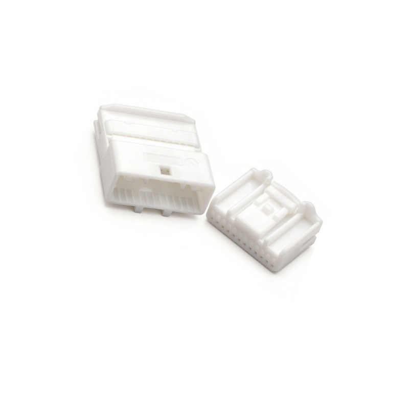
In electrical engineering terminology, pitch refers to the precise physical distance measured from the exact center of one pin cavity to the center of the adjacent pin. Universally measured in millimeters within modern automotive design, this metric dictates the compatibility and overall footprint of any connector system.
Pitch directly correlates with electrical capacity and physical density. A larger pitch provides greater spatial separation between conductive elements. This enhanced spacing increases dielectric strength, a necessity for high-voltage and high-current applications to prevent dangerous electrical arcing and heat buildup.
For example, when routing signals for complex control modules, engineers often specify components like a 2.2mm pitch 24P wire-end female housing. This specific 2.2mm spacing strikes an optimal balance. It offers sufficient density to pack 24 individual circuits into a compact dashboard space while maintaining enough isolation to prevent cross-talk between sensitive sensor wires.
Selecting the correct pin count requires a precise audit of your circuit needs. You must systematically count the exact number of power, ground, and data wires required for a specific subsystem. However, seasoned harness builders rarely buy a housing with the exact number of pins they currently need.
Best practices in automotive wiring dictate planning for future upgrades or diagnostic access. Engineers frequently specify housings with a slightly higher pin count than immediately necessary. The unused cavities are then intentionally blocked using specialized silicone dummy plugs or cavity seals. This proactive approach allows for seamless future additions—like integrating auxiliary lighting or a new temperature sensor—without requiring a complete teardown and replacement of the connector.
Pitch Size | Typical Pin Count | Primary Automotive Application | Design Focus |
|---|---|---|---|
1.20mm - 1.50mm | 12P - 60P | Infotainment displays, ADAS sensors | Low Current, High Data Speed |
2.20mm - 2.54mm | 8P - 24P | Interior lighting, ECU interfaces | Medium Current, Signal Mix |
3.00mm - 5.00mm+ | 2P - 8P | Headlights, Alternators, EV Power lines | High Current, Power Delivery |
Standard friction-fit connectors commonly found inside desktop computers are entirely unsuitable for automotive use. The constant harmonic vibration from a running engine, coupled with the violent physical shock of driving over potholes, inevitably causes friction-fit housings to back out and disconnect. Furthermore, relentless thermal expansion and contraction in the engine bay can loosen a terminal grip over time. This leads to micro-fretting corrosion and eventual circuit failure.
To combat this dynamic environment, automotive housings employ sophisticated multi-stage mechanical locking systems. The first line of defense is the Primary Lock. This consists of exterior latch-and-click mechanisms molded directly into the shell. When you push the two halves together, you feel and hear a distinct click confirming the initial mating.
Building on this foundation, secondary locks are introduced to secure the internal components. Terminal Position Assurance utilizes secondary plastic inserts or wedges that slide into the housing after the wires are inserted. They ensure the metal contacts are fully seated in their cavities and physically lock them in place, preventing wires from pulling out under tension. Finally, Connector Position Assurance is an additional sliding tab located on the exterior of the mated housings. Once engaged, it physically blocks the primary latch from being depressed. This guarantees the two halves cannot accidentally separate due to vibration or accidental impact.
In complex electrical architectures, multiple connectors sharing the exact same pitch and pin count are often located in close proximity. To prevent a technician from plugging a high-amperage power line into a sensitive low-voltage sensor module, manufacturers rely on mechanical keying. This involves molding specific ridges, slots, and asymmetrical shapes into the interior and exterior of the housing. This physical geometry ensures a plug can only be inserted in the correct orientation. More importantly, it restricts the plug exclusively to its designated receptacle.
Automotive manufacturers pair mechanical keying with strict color-coding standards. For example, the widely used Fakra standard assigns specific colors to specific mechanical profiles like Water Blue for neutral or Curry Yellow for IF radio. This visual management system drastically speeds up assembly line production. Instead of squinting at tiny plastic grooves, assembly workers and mechanics can instantly identify matching pairs, drastically reducing the risk of human error.
From a practical standpoint, custom harness builders and repair technicians should heavily utilize keyed and color-coded connectors. When you are working blindly under a dark dashboard, relying on a color-coded keying strategy acts as a critical safety net. By assigning specific keyways to specific subsystems, you ensure components cannot be accidentally cross-mated. This prevents catastrophic short circuits that could instantly destroy an expensive electronic control unit.
A common and incredibly frustrating engineering mistake is assuming any metal terminal will fit into any plastic shell. Housings and terminals are engineered as highly specific, proprietary matched systems. You cannot mix brands or product families. Attempting to force a terminal from one manufacturer into a housing designed by another results in poor contact retention, increased electrical resistance, terminal push-out during mating, and eventual failure.
When finalizing your selection, you must verify that the cavity diameter is wide enough to accept the total outer diameter of your wire after the terminal has been crimped. Automotive wire insulation varies wildly in thickness. If the insulation on a thicker wire is too bulky, it prevents the terminal from fully seating inside the cavity. This renders the secondary lock completely useless and leaves the connection vulnerable.
Automotive circuit boards require incredibly robust connection points. When routing a harness directly to a control module, the female plug housing must flawlessly mate with the male PCB headers soldered onto the board. You must verify that the pitch, keying, and locking latch perfectly align. Even a slight mechanical mismatch here causes severe stress on delicate solder joints, leading to micro-fractures, intermittent electrical faults, and a dead module.
Unsealed variants are designed exclusively for protected environments, primarily inside the vehicle cabin. Applications such as under-seat wiring, dashboard electronics, HVAC controls, and interior lighting face minimal exposure to moisture and dirt. Utilizing unsealed housings in these dry zones saves valuable space, reduces harness weight, and lowers overall manufacturing costs without compromising reliability.
Any connection located in the engine bay, routed along the exposed chassis, or integrated into exterior lighting assemblies must utilize sealed connectors. These ruggedized housings achieve high ingress protection ratings through a combination of individual silicone wire seals that compress tightly around the wire insulation and radial perimeter seals that compress between the mating housing halves. These elastomers create an impenetrable barrier protecting delicate contacts from driving rain, road salt, engine oil, and high-pressure washdowns.
Before attempting to replace cracked or melted automotive connector housings, objective identification is required. Grab a pair of digital calipers to measure the pitch accurately from center-hole to center-hole. Count the total number of pin cavities, including the empty ones. Note the external color and the specific arrangement of the mechanical keying slots to ensure you source the exact replacement from the catalog.
Executing a clean, professional repair requires specialized tooling. Attempting to pry things apart with a flathead screwdriver will only cause further damage. You will need a set of precision terminal release tools commonly known as depinning tools, high-quality wire strippers, and a ratcheting crimper specifically calibrated for the terminal family you are working with.
If the original plastic shell is shattered but the internal metal contacts remain shiny and free of corrosion, you can usually save the harness without cutting any wires.
First, safely disconnect the vehicle battery. Carefully pry off the external sliding latch and slide out the internal locking wedges from the damaged shell. Insert the appropriate depinning tool into the front face of the connector cavity to gently depress the internal retaining tang of the terminal. While depressing the tang, pull the wire lightly from the rear. The terminal should slide out smoothly. Align the extracted terminal with the corresponding cavity on your fresh housing, paying close attention to orientation markers. Push it in until you feel and hear a distinct click. Once all wires are transferred, reinstall the new secondary locks to secure the assembly.
Choosing the right structural shell for your automotive wiring is a delicate balancing act. It requires carefully measuring the pitch, anticipating the correct pin count for future needs, ensuring robust locking mechanisms are present, and strictly matching keying styles to prevent assembly disasters.
Most importantly, you must always view the housing, the internal contacts, and the mating headers as a single unified ecosystem rather than isolated parts. Taking the time to select precise components for your specific environmental and electrical load prevents frustrating diagnostic nightmares and ensures your vehicle systems run flawlessly in the harshest conditions.
Whether you are designing a complex harness for a new electric vehicle platform or repairing a critical engine control circuit, sourcing reliable components is paramount. Explore a comprehensive range of industry-standard connector housings, terminals, and headers directly at Jinkeji to guarantee professional-grade electrical performance.
To get an accurate measurement, use digital calipers to measure the distance from the exact center of one pin hole to the center of the one directly adjacent to it. Do not measure from the inner or outer edges of the holes. This yields an inaccurate pitch reading and leads to purchasing incompatible parts.
Yes, provided the old housing is simply physically cracked and the metal terminals inside are entirely free of corrosion, heat damage, or physical deformation. You can use a specialized depinning tool to extract them and snap them directly into an identical replacement shell without needing to cut and strip the wires.
Terminal Position Assurance is an internal plastic wedge or insert that keeps individual wires and metal terminals locked securely inside their specific cavities. Connector Position Assurance is an external sliding latch that keeps the two main plastic housing halves locked together. This prevents the entire plug from vibrating loose from its receptacle.
In almost all modern automotive standards, the color matters significantly. Different colors usually correspond to different mechanical keying profiles, consisting of internal notches and external ridges. This color-coded system is intentionally designed to physically prevent you from plugging a wire harness into the wrong module, which could cause a catastrophic short circuit.
Manufacturers typically use high-performance engineering polymers like Polyamide, commonly known as Nylon, or Polybutylene Terephthalate. These specialized materials are chosen for their exceptional resistance to extreme temperatures, chemical exposure, and the intense mechanical stress found in engine bays.
The choice depends entirely on the installation environment. If the connection will be exposed to the elements, such as in the engine compartment or under the chassis, a sealed housing with silicone gaskets is mandatory to prevent water ingress. For protected interior cabin locations like under the dashboard, unsealed housings are perfectly adequate and help save valuable space.


