

Views: 0 Author: Site Editor Publish Time: 2026-10-26 Origin: Site


Modern vehicles are essentially computers on wheels. As complex automotive systems demand increasingly reliable data transmission, engineers face a persistent packaging dilemma. They must fit more electrical connections into microscopic structural spaces. High-density interfaces solve this exact problem. In this comprehensive engineering and procurement guide, you will learn how to strategically select ECU connectors, comparing configurations from 16-pin to 40-pin to future-proof your vehicle architectures.
Central Nervous System: Electronic Control Unit interfaces dictate vehicle safety, signal integrity, and overall module performance.
Application-Specific Pin Counts: Selecting the appropriate configuration ranging from 16-pin to 40-pin depends entirely on operational complexity, bridging basic body control units to high-speed telematics.
Rigorous Testing Standards: Components must strictly adhere to automotive-grade validations like USCAR-2 and LV214, ensuring resistance against extreme vibration, thermal shock, and moisture ingress.
Integration Matters: The choice of printed circuit board mounting style, such as Surface Mount, Through-Hole, or Press-fit, is equally as critical as the pin count for maintaining long-term durability.
Historically, automotive architectures relied on decentralized systems where individual functions possessed their own dedicated, low-pin-count modules. Today, industry analysts note a massive paradigm shift in modern automotive wiring. As manufacturers aggressively transition from decentralized modules to Zonal Architectures and central domain controllers, the sheer volume of data generated by LiDAR, high-resolution cameras, and complex electric vehicle battery management systems is skyrocketing.
This industry-wide trend dictates a rapid departure from legacy low-pin headers. Consolidating multiple vehicle functions into a single centralized module necessitates the use of high-density interconnects. A modern domain controller must simultaneously handle dozens of sensor inputs, high-current power lines, and multiple communication protocols including CAN-FD, LIN, and Automotive Ethernet. Utilizing traditional low-density interfaces is no longer physically feasible due to strict weight and space constraints within the vehicle chassis. Upgrading to high-density connector architectures has become an essential engineering requirement for ensuring sufficient bandwidth for next-generation autonomous and electric vehicle technologies.
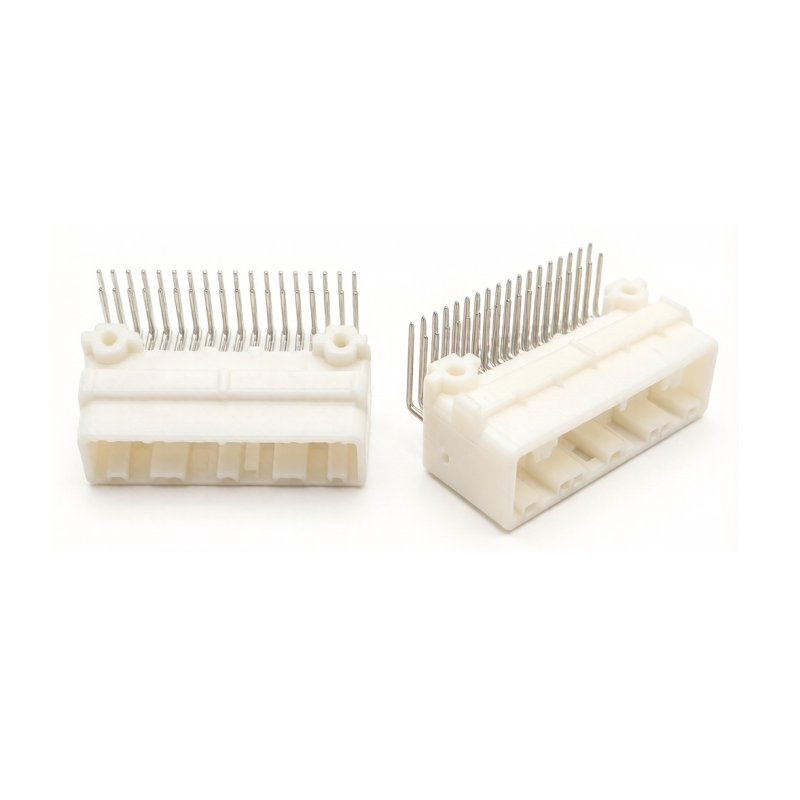
Selecting the correct pin configuration is a critical architectural decision that heavily impacts printed circuit board real estate, thermal management, and signal integrity. Below is an objective engineering breakdown of common high-density interfaces to guide your component sourcing.
Typically deployed in applications requiring moderate input and output capabilities, 16P connectors serve as the industry standard for basic Body Control Modules. These units manage localized functions such as door locks, window lifters, seat adjustment motors, and wiper controls.
Because these localized systems primarily handle power distribution and low-speed switching signals, they often utilize a larger pitch like 2.54mm to accommodate thicker wire gauges capable of carrying 5 to 15 amps per pin. They offer a compact footprint while maintaining the robust power delivery and mechanical peel strength required for frequently actuated body systems.
Moving upward in complexity, mid-range pin counts represent the versatile middle ground in automotive electronic design. Engineers frequently specify 20-pin and 28-pin interfaces for HVAC control units, exterior LED lighting management, and basic engine management systems.
These configurations provide an optimal balance between space-saving design and multi-signal capacity. A 28-pin interface allows engineers to partition the layout into dedicated zones, isolating high-current power pins on one side from sensitive analog sensor inputs on the other. This physical isolation is a highly effective strategy for preventing electromagnetic interference and signal crosstalk.
As system complexity scales significantly, 32P connectors become the go-to standard for demanding applications like telematics gateways, transmission control units, and Battery Management Systems.
In a battery management application, the interface must handle precise micro-volt cell monitoring alongside thermal sensor data. These components are highly valued for their ability to support mixed configurations. A single housing can integrate large terminal blades for power delivery alongside micro-terminals for high-speed digital communication, drastically reducing the total number of headers required on the logic board.
At the top tier of interconnect density, 40-pin configurations are strictly reserved for the most data-intensive computing modules. These include central ADAS processing units, radar fusion modules, and high-end infotainment hubs. For instance, utilizing a 2.2mm pitch 40P board connector provides an exceptional balance, offering enough spatial separation for high-voltage isolation while maintaining a tight enough density to fit within compact aluminum module housings.
These cutting-edge applications require the transmission of uncompressed video and high-speed sensor data in real-time. In these environments, the headers are meticulously designed with strict impedance control, specialized internal shielding, and differential pair layouts to support Automotive Ethernet protocols. Emphasizing data throughput, they utilize specific pitches to maximize pin density without expanding the module's physical footprint.
Pin Count | Typical Pitch Range | Primary Automotive Application | Key Engineering Challenge |
|---|---|---|---|
16P | 2.20mm - 2.54mm | Body Control Modules, Window/Door Logic | Mechanical peel strength during wire harness routing |
20P / 28P | 1.80mm - 2.20mm | HVAC, LED Lighting, Engine Management | Isolating power pins from low-voltage sensor inputs |
32P | 1.27mm - 2.20mm | Telematics Gateways, Battery Management Systems | Managing mixed terminal sizes for power and data |
40P | 0.50mm - 2.20mm | ADAS Domain Controllers, LiDAR Fusion | Impedance control and thermal heat dissipation |
Sourcing the correct business-to-business components requires a rigorous evaluation of technical specifications. Procurement teams and hardware engineers must evaluate the following parameters to ensure absolute system reliability under severe road conditions.
The foundational metric for any interconnect is its electrical capacity. Engineers must calculate the maximum continuous current carrying capacity and apply appropriate thermal derating curves. Cramming 15 amps through a densely packed header can cause localized temperature spikes, leading to plastic housing degradation.
Furthermore, voltage rating and dielectric withstanding voltage are increasingly critical, especially in electric vehicle architectures where system voltages push past 800 volts. For telematics, data rate capabilities are paramount. The interface must maintain a specific characteristic impedance, typically 100 ohms for Ethernet or 120 ohms for CAN bus, to minimize insertion loss, return loss, and data packet drops.
Automotive environments are notoriously unforgiving. Headers mounted in the engine compartment or under the chassis require stringent environmental sealing, typically rated at IP67 for temporary immersion or IP69K for high-pressure and high-temperature washdown.
Temperature classification is another vital factor. Depending on the mounting location, components must withstand extreme thermal cycling. Industry standards require parts to operate reliably from negative 40 degrees up to 125 degrees Celsius or even 150 degrees Celsius for direct engine-mount applications. Consequently, housing materials such as high-temperature Polyamide or Liquid Crystal Polymer must be specified.
Vibration profiles vary drastically across a vehicle. A chassis-mounted module experiences entirely different mechanical shock frequencies than a cabin-mounted infotainment unit. To prevent fretting corrosion and accidental un-mating during heavy vibration, automotive interfaces utilize specialized secondary locking mechanisms.
Terminal Position Assurance utilizes a plastic insert to ensure terminals are fully seated and locked into the housing, preventing pins from backing out. Connector Position Assurance acts as a secondary lock on the exterior, guaranteeing the male and female halves are completely mated and cannot vibrate loose on rough terrain.
Pitch dictates the overall footprint of high-pin-count connectors on the logic board. While a 2.54mm pitch offers excellent mechanical robustness, it consumes significant board space.
In contrast, a tighter pitch drastically reduces the footprint, enabling the design of miniaturized domain controllers. However, tighter pitches require far stricter manufacturing tolerances and reduce the physical isolation between pins, complicating printed circuit board routing and high-voltage isolation strategies.
The reliability of an automotive system relies not only on the header itself but on how it physically integrates with both the logic board and the external wiring infrastructure.
The mounting methodology becomes a critical failure point if not specified correctly. Through-Hole Technology remains the gold standard for applications subjected to severe mechanical shock, as pins soldered completely through the board ensure the header will not detach during continuous engine vibration.
Surface Mount Technology is highly favored for modern telematics and ADAS modules. Because these components only occupy the top layer of the board, engineers can utilize the inner layers for complex signal routing, which is crucial for impedance control. Press-Fit Technology offers a solderless alternative, relying on compliant pins that compress into plated through-holes. This creates a highly reliable and gas-tight connection immune to thermal fatigue, often preferred in critical electric vehicle inverters.
The male header on the board is only as reliable as the female plug it mates with. Achieving optimal performance requires precise compatibility with the vehicle's external wiring. When integrating these systems, sourcing a precisely engineered Automotive Wire Harness is absolutely essential.
Improper crimping leads to increased electrical resistance, localized heating, and eventual terminal failure. High-density interfaces require ultra-precise crimp validation. The terminal must securely grip both the wire conductor and the insulation without piercing the latter, ensuring strain relief and preventing moisture ingress from traveling down the wire jacket.
Procurement teams cannot rely on standard consumer electronics specifications when sourcing components for vehicle architectures. Using non-compliant parts exposes manufacturers to catastrophic field failures and multimillion-dollar recalls.
Developed by the United States Council for Automotive Research, USCAR-2 is the premier performance standard for automotive electrical systems in North America. It outlines rigorous testing procedures designed to validate mechanical engagement force, thermal shock resilience, and electrical continuity under severe multi-axis vibration.
LV214 is the stringent European equivalent, developed jointly by major German automakers. It places heavy emphasis on terminal crimp quality and contact physics. LV214 is particularly unforgiving regarding fretting corrosion, a phenomenon where microscopic vibrations cause contact surfaces to rub and wear away protective plating. Passing LV214 dynamic resistance testing is non-negotiable for safety-critical data interfaces.
Even with a strong understanding of technical specifications, engineering teams can make strategic errors during the selection process. Avoiding these common pitfalls prevents costly redesigns and assembly line bottlenecks.
A frequent architectural error is selecting a header with significantly more pins than currently required. Utilizing a 40-pin header for an application that only requires 24 active circuits is highly inefficient. It wastes valuable logic board real estate and unnecessarily inflates the bill of materials cost. Conversely, under-specifying forces engineers to route high-current power lines adjacent to sensitive low-voltage data lines within a confined pitch, causing severe electromagnetic interference issues.
Another major oversight is ignoring assembly line ergonomics. In a controlled laboratory, mating a dense plug is straightforward. On a fast-paced assembly line, it is a different reality. Imagine a technician reaching blindly behind a dashboard. Without physical keying or scoop-proof designs, bent pins are inevitable. Procurement must evaluate if the design features robust guide ribs and lead-in chamfers to ensure proper alignment before electrical contacts engage.
Choosing the correct ECU interfaces is a complex balancing act of board space, electrical demands, and environmental ruggedness. As the automotive industry accelerates toward autonomous driving and electrification, high-density components are no longer optional. They are the critical backbone of next-generation vehicles. By carefully evaluating pitch sizes, mating ergonomics, and rigorous testing standards, engineering teams can ensure long-term safety and optimal vehicle performance.
When you are ready to finalize your architecture, exploring a robust portfolio of engineered solutions from Jin Ke Ji Connectors ensures your domain controllers meet strict automotive standards. Whether you need a robust 16-pin header for body controls or a high-speed 40-pin interface for ADAS, partnering with an experienced manufacturer guarantees reliable data transmission across your entire vehicle platform.
Automotive ECU interfaces are engineered specifically for severe operational environments. Unlike standard consumer electronics, they utilize specialized secondary locking mechanisms like Terminal Position Assurance and Connector Position Assurance. They are also validated against rigorous vibration, thermal shock, and moisture standards such as USCAR-2 and LV214 to prevent failure on the road.
Yes, but it is generally inefficient from an engineering standpoint. Utilizing an oversized interface consumes unnecessary board real estate, increases the required insertion force on the assembly line, and adds unnecessary weight and cost. It is far more practical to select a properly sized interface unless you are specifically planning for imminent module expansion.
They manage high-speed signals through ultra-precise pitch spacing, controlled impedance designs, and integrated internal shielding. Manufacturers carefully map the pin layouts to physically separate power lines from sensitive data lines, effectively minimizing electromagnetic interference and signal crosstalk.
Pitch size directly determines how much physical space the component occupies on the printed circuit board. A smaller pitch allows engineers to pack more connections into a miniaturized housing, which is vital for modern, space-constrained domain controllers. However, tighter pitches require stricter manufacturing tolerances and make high-voltage isolation more challenging to design.
The maximum current rating depends heavily on the terminal size, wire gauge, and the overall thermal derating curve of the specific housing. While individual micro-pins in a dense layout might only handle 3 to 5 amps for data transmission, mixed-layout connectors can feature dedicated power blades capable of carrying 15 to 30 amps safely, provided the heat dissipation is managed correctly.


