

Views: 0 Author: Site Editor Publish Time: 2026-07-27 Origin: Site


Modern vehicles have transformed far beyond their mechanical roots. They now function as sophisticated, highly integrated rolling data centers. This evolution demands flawless signal transmission and robust power routing across every subsystem. Automotive connectors act as the vital electromechanical interfaces bridging a vehicle's electrical and electronic networks. As automakers shift from basic electrical routing to complex data architectures like ADAS and EV powertrains, component selection carries immense weight. You cannot treat these interfaces as mere commodity purchases. Choosing the wrong component introduces severe risk-management failures, impacting assembly scalability, warranty claim rates, and overall system safety. You need a rigorous, proactive approach to specify these components. This guide provides a structured, standards-based framework for evaluating and shortlisting components effectively. We will explore essential connector categories, structural requirements, and precise validation protocols you need for long-term reliability.
Electrical connectors represent a surprisingly high percentage of field failures in modern vehicles. When engineers evaluate system architectures, they must prioritize physical mating integrity. The cost of failure extends far beyond a single broken pin. Poor connections trigger intermittent faults. They disrupt communication networks and confuse diagnostic systems. In extreme cases, high electrical resistance leads to localized heating and thermal events. These failures drive up warranty costs and trigger damaging mass recalls. Reliable mating is completely non-negotiable.
Engineers do not evaluate components in a vacuum. Industry standards provide a rigid baseline for performance. In North America, the USCAR-2 standard dictates testing protocols for automotive electrical connection systems. European manufacturers rely on the LV214 standard. These frameworks force suppliers to test products under extreme thermal, mechanical, and electrical stress. Specifying a connector lacking these certifications introduces massive design risk. You must request full validation reports from suppliers before integrating any new housing or terminal family.
The transition to software-defined vehicles (SDVs) and electric vehicles (EVs) has completely rewritten wiring schematics. Historically, a vehicle relied on basic point-to-point analog wiring. Today, requirements have bifurcated into two specialized categories. First, high-voltage power transmission supports traction motors and battery packs. Second, high-speed data transfer feeds autonomous driving sensors and digital displays. This split forces engineers to master distinct physical interfaces. You must choose specialized components engineered specifically for either immense power loads or delicate gigabit signals.
Common Mistake: Relying on legacy industrial connectors for modern automotive applications. Industrial components rarely survive continuous engine vibration or the wide temperature swings inherent to automotive environments.
Engineers must match the physical connector to the precise electrical task. Using an overly complex interface wastes money. Specifying a substandard interface guarantees failure. We can categorize the most critical interfaces based on their application.
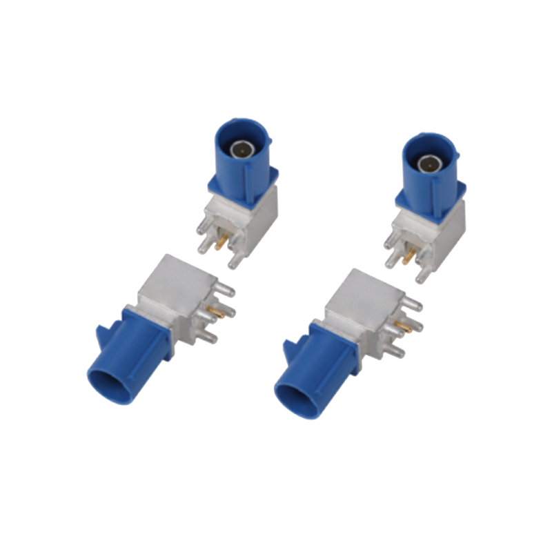
Telematics, GPS, automotive radar, and advanced driver-assistance systems (ADAS) rely on constant radio-frequency communication. These systems require strict impedance control and shielded pathways. Standard pin-and-socket housings cannot handle RF signals. Instead, engineers use specialized coaxial interfaces. FAKRA Connectors dominate this space. They feature a unique standardized color-coding system. They also utilize highly specific mechanical keying. This design physically prevents workers from mis-mating cables on a fast-paced assembly line. A blue GPS cable will only mate with a blue GPS receptacle. This fool-proof assembly reduces manufacturing errors to near zero.
Infotainment displays, high-definition camera systems, and USB/LVDS data links require a different approach. These systems push massive amounts of digital data rather than analog RF signals. They utilize HSD Connectors (High-Speed Data). These multi-pin interfaces feature robust, shielded impedance-controlled performance. The metal shielding prevents electromagnetic interference (EMI) from disrupting data packets. EMI protection is absolutely vital in modern vehicles. Surrounding power cables generate strong magnetic fields. Unshielded data lines will drop packets, causing screen flickers or camera lag.
Environmental exposure dictates the physical housing design. You must evaluate where the module lives within the vehicle chassis.
Electric vehicle battery management systems, inverters, and fast-charging ports handle lethal voltages. These interfaces exceed 400V or 800V. Safety takes absolute precedence. HV components require bright orange housings for visual identification. They must include robust electromagnetic shielding. More importantly, they feature a High Voltage Interlock Loop (HVIL). The HVIL uses a secondary low-voltage circuit. If a technician unplugs the connector, the HVIL breaks first. This signals the main contactors to shut off high-voltage power before the main pins separate. This prevents dangerous electrical arcing.
Table 1: Application Matrix
| Connector Category | Primary Use Case | Key Evaluation Feature |
|---|---|---|
| RF / Analog | GPS, Radar, Telematics | Mechanical keying and color-coding |
| High-Speed Data | Cameras, LVDS, Displays | Shielded impedance control |
| Harsh Environment | Engine bay, Chassis | IP67/IP69K sealing systems |
| High-Voltage Power | EV Inverters, BMS | HVIL safety mechanisms |
A connector is only as reliable as its physical termination. You cannot evaluate a housing without considering the cable attached to it. The metal terminal inside the plastic body must be precision-matched to the specific Automotive Wire. Mismatching these elements ruins harness integrity.
Current-carrying capacity dictates the required wire size. We measure this in AWG (American Wire Gauge) or square millimeters (mm²). High current demands thick copper conductors. Thick conductors require large metal terminals. Large terminals dictate a bulky plastic housing. You must finalize your electrical load requirements first. Once you define the wire size, your housing options immediately narrow. Forcing a thick cable into an undersized terminal results in broken copper strands. This drastically increases electrical resistance and heat.
Automotive environments subject cables to intense heat, oil, and abrasion. Engineers use specialized cross-linked insulation, such as TXL, GXL, or XLPE. The insulation type dictates the outer diameter of the cable. This outer diameter plays a critical role in sealed connections.
Sealed housings rely on silicone wire seals to block water. The seal must grip the wire insulation tightly. If you specify thin-wall TXL wire but use a seal designed for thick-wall GXL wire, water will bypass the seal. Moisture ingress corrodes the copper terminals. Corrosion leads to intermittent electrical failures. You must match the seal inner diameter to the wire outer diameter perfectly.
Proper termination requires precise crimping. You need secondary tooling specifically designed for your chosen terminal family. Implementing a new connector style carries production risks.
Failing to execute these steps compromises crimp integrity. This transforms a high-quality connector into a major failure point.
Engineers face thousands of product options from dozens of suppliers. You need an objective framework to narrow down choices. Evaluation requires balancing electrical demands, environmental stress, and assembly feasibility.
Start by determining the operating voltage and the maximum continuous current. However, a static current rating is useless in an automotive environment. You must evaluate the component's derating curve. As ambient temperature rises inside an engine bay, the connector's ability to dissipate heat drops. A terminal rated for 15 amps at room temperature might only carry 8 amps at 105°C. Ignoring the derating curve guarantees the plastic housing will melt under peak loads.
Vibration destroys poor electrical connections. You must classify the vibration profile. A sensor mounted directly to an internal combustion engine experiences brutal high-frequency shaking. A module inside the cabin experiences low-frequency, dampened movement. You must match the terminal contact force to the vibration severity. High vibration requires strong terminal spring pressure to prevent microscopic breaks in the electrical circuit.
Temperature classifications matter equally. Cabin interiors may only require a -40°C to +85°C rating. Under-hood applications often demand +125°C or +150°C capabilities. Furthermore, you must verify chemical resistance. The housing plastic must resist degradation when exposed to engine oil, brake fluid, transmission fluid, and antifreeze coolants.
A well-designed component must assemble easily by hand. If a plug requires too much physical force to mate, line workers will suffer ergonomic fatigue. High mating force leads to partially seated connections. To solve this, premium components feature two critical locking mechanisms:
Finally, consider blind-mating capabilities. Workers often route harnesses into dark, hard-to-reach areas like door panels or behind dashboards. Connectors featuring chamfered edges and lead-in funnels help guide the halves together without direct visual sightlines.
Decision Framework Chart
| Criteria Group | Primary Evaluation Metric | Design Implication |
|---|---|---|
| Electrical | Derating Curves | Determines true current capacity at peak heat. |
| Environmental | Vibration Profiles | Dictates terminal spring force and plating material. |
| Assembly | TPA / CPA Locks | Reduces warranty claims from partially seated plugs. |
| Ergonomics | Mating Force Limits | Prevents worker fatigue during high-volume production. |
Selecting a component on paper represents just the first step. Rigorous validation ensures the physical hardware survives the real world. Quality control protects your production lines and your end customers.
Never rely solely on a datasheet. You must request extensive test reports from the manufacturer. Look for specific USCAR-2 or LV214 test results. Thermal shock testing subjects the housing to rapid temperature swings, exposing plastic cracking. Salt spray tests run for 48 to 96 hours to simulate road salt exposure. They verify the terminal plating resists corrosion. Mechanical drop tests ensure the locking tabs survive handling impact on the factory floor.
Validation continues after a supplier builds the harness. The chosen connectors must support automated harness testing. Electrical continuity testing verifies every pin connects to the correct destination. Hi-pot (high potential) testing applies massive voltage to check for insulation leaks between adjacent wires. Pull-force testing confirms the crimped terminals remain securely attached. Connectors lacking accessible test points slow down automated quality control.
A technically perfect component fails if you cannot buy it. Evaluate vendor reliability and global lead times. Single-sourcing a proprietary interface exposes your production line to severe bottlenecks. Additionally, evaluate the availability of secondary tooling. Do multiple manufacturers produce the crimping applicators needed for this specific terminal? If not, you may face expensive delays outfitting your harness manufacturing facilities. Choose component families with broad industry adoption to mitigate sourcing risks.
Automotive electrical architecture relies entirely on the integrity of its physical connections. Connector selection remains a highly complex exercise. You must balance electrical demands, extreme environmental realities, and rigid manufacturing constraints.
Take proactive next steps in your design process. Advise your engineering teams to secure CAD models and physical samples immediately. Build prototype harness sections to test routing and mating ergonomics. Consult with supplier application engineers to review your specific environmental challenges before finalizing your bill of materials.
A: FAKRA is typically a single-coaxial interface designed for analog radio-frequency applications, telematics, and GPS. HSD (High-Speed Data) is a multi-pin, heavily shielded interface engineered specifically for high-speed digital data transmission, such as LVDS streams for cameras and infotainment displays.
A: Evaluate the mounting location. Use IP67 for areas exposed to splashing or temporary submersion, like lower chassis runs. Specify IP69K for engine bays or wheel wells where components face high-pressure, high-temperature washdowns or direct road spray. Unsealed components suit protected cabin interiors.
A: Terminal Position Assurance (TPA) guarantees metal terminals sit fully locked inside the plastic housing. Connector Position Assurance (CPA) guarantees the two mating halves remain locked together. They eliminate partial seating errors and prevent high-vibration environments from shaking connections loose, drastically reducing warranty claims.
A: No. Automotive-grade cross-linked wire (like TXL or GXL) is strictly required. Standard commercial PVC wire melts under under-hood temperatures. It also lacks resistance to harsh chemicals like engine oil and brake fluid. Automotive wire ensures proper sealing and thermal survivability.
![[174928-1] 3.5 Pitch, 3P White Housing](http://iororwxhimpllk5p-static.micyjz.com/cloud/lrBpkKlmliSRollpqnrkkp/22-640-640.jpg "[174928-1] 3.5 Pitch, 3P White Housing")


