

Views: 0 Author: Site Editor Publish Time: 2026-10-09 Origin: Site


Picture this. You have just spent weeks finalizing a complex circuit design. Suddenly, you realize a poorly chosen interconnect is causing intermittent power drops. This is a nightmare scenario for any field engineer. Choosing the wrong setup does more than waste valuable enclosure real estate. It actively invites short circuits and long-term mechanical failures.
In this comprehensive guide, we will unpack the ongoing debate between different connector architectures. By exploring their mechanical differences, ideal use cases, and installation nuances, we will help you make a rigorous, data-driven choice for your next build.
Board-mounted interconnects route power and signals directly from external wiring to a Printed Circuit Board. They are highly efficient for compact electronic devices.
Inline cable connectors join two separate cable harnesses mid-air. They are the standard for long-distance routing in industrial environments.
The primary decision factors include spatial constraints, field maintenance requirements, and central system architecture.
Proper installation utilizing high-quality crimp components is strictly required to ensure long-term reliability.
At their core, wire-to-board connectors serve as the critical infrastructure bridging external peripherals directly to a Printed Circuit Board. These peripherals often include motors, sensors, batteries, or power supplies. This architecture allows a device to communicate with the outside world while maintaining a centralized processing hub.
The mating process of these interconnects involves two distinct halves. The first half is a rigid header. This header is permanently soldered onto the flat board using either Surface Mount Technology or Through-Hole Technology. The second half is a plastic receptacle housing attached to the end of a stripped cable. Specifically, when the receptacle is pushed into the header, the metal contacts engage to establish a secure electrical circuit. If you are designing a system that requires reliable power delivery to a microchip, utilizing these board-mounted components is standard engineering practice.
Take high-power applications as a practical example. Engineers frequently specify a vertical type power socket wafer featuring a 6.35mm pitch. This specific spacing prevents electrical arcing while handling substantial thermal loads, ensuring safe and continuous power delivery to the main circuitry.
Space Efficiency: Because they boast an exceptionally small footprint, these components are a lifesaver for developers wrestling with high-density layouts.
Assembly Automation: Headers can be seamlessly placed using automated pick-and-place machinery. This significantly lowers manufacturing costs.
Signal Integrity: By terminating directly at the source, they reduce signal degradation and minimize messy cable clutter inside the device enclosure.
Modification Difficulty: In contrast to modular setups, once the header is soldered, changing the connection type requires desoldering. This is highly impractical for field repairs.
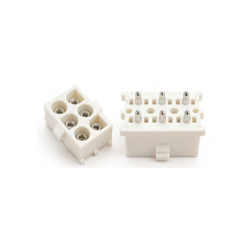
Operating entirely independently of a circuit board, wire-to-wire connectors are engineered to join two free-hanging cables together. This modular approach is absolutely vital for bridging long distances. It is equally important for passing electrical currents through physical barriers, such as a heavy machine chassis or a structural wall.
The mechanism relies on two mating housings, typically a plug and a receptacle. Both housings contain metal contacts attached to stripped cable ends. When pushed together, the housings interlock securely. Furthermore, many modern designs feature positive locking latches. These latches prevent accidental disconnection caused by pulling forces. For harsh environments, these housings often integrate silicone seals to actively block moisture and dust ingress.
Ultimate Flexibility: They allow cable harnesses to be routed freely through three-dimensional spaces without being tethered to a flat surface.
Maintenance Efficiency: Technicians can easily unplug a faulty component and plug in a replacement. They never have to touch the sensitive central processing unit.
Durability: They can be housed in thick, weather-resistant materials. This makes them perfectly suited for extreme environmental conditions.
Physical Bulk: The mating housings are generally larger and heavier than their board-mounted counterparts. Consequently, they require more physical clearance.
Understanding the exact differences between these two systems is vital for long-term reliability. The table below outlines the primary engineering distinctions.
Feature | Board-Mounted Connectors | Inline Cable Connectors |
|---|---|---|
Primary Function | Terminates external cables directly to a main circuit board. | Joins two free-hanging cables inline. |
Form Factor | Rigid, low-profile, and fixed to a flat surface. | Flexible, bulky, and floating. |
Mounting Method | Soldered on one side, crimped on the other. | Crimped on both sides. |
Maintenance | Difficult. Requires accessing the internal device enclosure. | Easy. Allows for quick disconnects in the field. |
Typical Pitch Sizes | 0.8mm, 1.0mm, 1.25mm, 2.0mm, 2.54mm, 6.35mm. | 2.54mm, 3.0mm, 4.2mm, 6.35mm and up. |
The physical footprint heavily dictates where each component can be utilized. Board-mounted systems are inherently rigid. The header is permanently anchored, meaning the connection point cannot move. This requires precise calculation of cable lengths to ensure the line reaches its destination without excessive tension. Conversely, inline systems are floating. They can be dynamically tucked into tight corners, routed through protective conduits, or left suspended between two anchor points.
Signal flow differs significantly between the two architectures. Board connectors act as a distribution point. Power or data enters the system and is immediately dispersed through copper traces to microprocessors, capacitors, and resistors. Inline setups, on the other hand, simply pass the signal along a continuous path. They act as a physical bridge. This ensures the voltage and current continue their journey to the final destination without altering the core routing logic.
From a lifecycle perspective, field accessibility is a major differentiator. Imagine a proximity sensor failing on a busy factory floor. If it relies on an inline setup, a maintenance technician simply unclips the housing. They swap the sensor and click a replacement into place within seconds. In contrast, if a board connection fails, that same technician must open the main device casing. They must navigate a maze of internal components and carefully extract the housing from the delicate header. This drastically increases the risk of damaging sensitive electronics.
Regardless of the plastic housing style you ultimately select, the actual transfer of electricity relies entirely on the internal metal contacts. In the vast majority of commercial applications, these contacts are secured to the copper core utilizing crimping technology.
A proper crimp is not merely a physical crushing of metal. Rather, it is a highly precise mechanical deformation. When applied correctly with calibrated tooling, crimp terminals create what engineers call a gas-tight seal. This means the copper core and the metal terminal are compressed so tightly that no oxygen or moisture can penetrate the microscopic gaps. Consequently, this prevents oxidation and corrosion. It ensures low contact resistance and reliable power delivery over the lifespan of the device. A poor crimp inevitably leads to parasitic resistance, dangerous heat generation, and eventual catastrophic failure.
While both systems rely heavily on crimping, the architecture of the terminals differs based on the mating mechanics. In board applications, the cable end typically features a female socket terminal. This smoothly slides over the exposed male pins soldered to the flat surface. In inline applications, one housing contains male pin terminals, while the opposing housing contains female socket terminals. Engineers must meticulously specify the correct gender for each housing to guarantee a successful mating cycle during final assembly.
Different industries have established distinct standards based on their unique operational environments and mechanical stresses. Analyzing current market trajectories reveals a fascinating split in interconnect engineering.
The explosion of smart home technology and interconnected devices is driving an intense demand for ultra-miniaturized solutions. Internal space is the most valuable commodity in consumer electronics. Laptops, smartphones, and smart sensors are designed to be as razor-thin as mechanically possible. Consequently, board-mounted connections dominate this field. Pitch sizes are frequently dropping to 1.0mm or less to save critical space and reduce overall device weight.
On the other end of the spectrum, the rapid expansion of the electric vehicle sector forces interconnects to handle unprecedented power densities. The transportation sector relies heavily on heavy-duty automotive connectors to route power dynamically. Power travels from the battery in the engine bay all the way to taillights at the rear. This necessitates long, modular cable harnesses. These harnesses are connected via sealed inline systems that can withstand severe engine vibration, thermal shock, and road moisture.
Industrial machinery operates in harsh environments fraught with high mechanical stress. A factory assembly line typically uses a central control cabinet. Inside this cabinet, board interconnects handle the delicate internal logic routing. Outside the cabinet, heavy-duty inline connectors link external robotic arms, proximity sensors, and conveyor motors. This strategic separation allows for the rapid replacement of battered external parts without exposing the central control panel.
The final decision dictates the reliability, manufacturability, and lifespan of your entire electrical architecture. Engineers must analyze several technical parameters before finalizing a purchase. Abstract concepts must be translated into concrete selection criteria.
The physical footprint available within your enclosure is often the primary deciding factor. If your design centers around a central printed circuit board, utilizing high-quality board-mounted components is the most efficient method for terminating external signals. They allow developers to pack multiple lines into a highly condensed area. In contrast, if real estate is severely limited or non-existent, routing the connection away from the main circuitry becomes strictly necessary. In these specific scenarios, inline configurations provide unparalleled spatial flexibility.
Electrical junctions are notoriously susceptible to environmental degradation. Assessing the operational climate is crucial for preventing galvanic corrosion and erratic short circuits. For applications exposed to moisture or chemical contaminants, the Ingress Protection rating is paramount. Look for robust outer shells designed to achieve IP67 or IP68 ratings.
Furthermore, vibration is a critical hazard. Constant kinetic energy can cause fretting corrosion at the contact interface. To combat this kinetic stress, high-reliability systems utilize positive locking latches and Terminal Position Assurance mechanisms. These features ensure the contacts remain firmly seated regardless of external shaking.
Electrical specifications dictate the physical size, contact material, and housing design. Exceeding the rated ampacity or voltage will inevitably lead to severe Joule heating, melted plastic housings, and potential fire hazards. Always examine the dielectric withstanding voltage alongside creepage and clearance distances. High-voltage applications require greater physical separation between adjacent pins to prevent electrical arcing.
Additionally, it is vital to match the capacity with the appropriate American Wire Gauge. If a terminal is not rated for the specific copper thickness used, the resulting connection will suffer from high contact resistance. Always consult the manufacturer derating curves to understand how current capacity drops as ambient temperatures rise.
Identifying the correct architecture is only the first step. Sourcing reliable components from reputable manufacturers is an equally critical hurdle. The current market is saturated with low-cost alternatives that severely lack the metallurgical consistency required for long-term safety.
Engineering teams should prioritize manufacturers that provide comprehensive technical documentation. Pay close attention to the base materials. Phosphor bronze offers superior spring characteristics and fatigue resistance compared to standard brass. Consider the plating material based on your unique environment. Tin plating is highly cost-effective for standard static environments. However, for high-reliability data transmission or high-vibration environments, gold-plated contacts are strictly recommended due to their exceptional oxidation resistance.
Compliance and safety certifications are absolutely non-negotiable for commercial projects. Ensure that the components you select comply with international environmental directives such as the Restriction of Hazardous Substances. Partnering with a manufacturer that enforces strict quality control, like Automated Optical Inspection during production, will drastically reduce your field failure rate.
Ultimately, choosing the right interconnect depends entirely on your specific project parameters. Use board-mounted headers for central electronic hubs where internal space is at a premium and automated assembly is possible. Conversely, rely on floating inline interconnects to extend long lines, navigate complex chassis layouts, and facilitate rapid field maintenance.
By carefully reviewing your spatial constraints, environmental hazards, and power limits, you can engineer a system built for absolute longevity. When you are ready to finalize your bill of materials, explore the high-performance interconnect solutions at JinKeJi. Selecting certified, rigorously tested components from a trusted brand ensures the ultimate safety and performance of your electrical architecture.
Generally, no. If your system architecture requires data signals or power to physically enter a printed circuit board for processing, you must utilize a board-mounted header or solder the lines directly. Inline configurations are strictly designed for joining two independent cable segments in mid-air and cannot interface directly with a flat circuit board.
The vast majority of visible automotive connectors are inline. They are essential for routing complex wiring harnesses throughout the vehicle chassis, doors, and engine bays. However, hidden inside the vehicle electronic control units, board-mounted headers are heavily utilized to connect those external harnesses to the internal computing hardware.
Yes. The most common and reliable termination method for the cable end of both categories involves using crimp terminals. A properly executed crimp creates a gas-tight micro-weld between the copper core and the metal contact, actively preventing oxidation. Crimping remains the undisputed industry standard for durability.
The maximum current depends entirely on the pitch size, contact material, and copper gauge. Micro-pitch headers typically handle between 1 to 3 amps per pin. However, heavy-duty power socket wafers, such as those with a 6.35mm pitch, can safely transmit upwards of 10 to 15 amps per pin. Always consult the specific derating curve provided by the manufacturer.
To prevent accidental decoupling in high-vibration environments, engineers specify housings equipped with positive locking latches. These latches physically click into place and require manual depression to release. Additionally, utilizing Terminal Position Assurance wedges ensures the internal metal contacts cannot vibrate loose from the plastic housing during operation.


