

Views: 0 Author: Site Editor Publish Time: 2026-10-01 Origin: Site


Shrinking circuit boards cause constant design headaches. Balancing limited board real estate with resilient power and signal integrity is a daily struggle. You are likely working with strict spatial limits in harsh environments. Picking the wrong terminal spacing ruins signal integrity. It complicates manufacturing. It wastes highly valuable space.
In electronic design, the exact distance measured from the center of one contact pin to the center of the adjacent pin acts as your foundational constraint. This measurement dictates your entire routing strategy. We will compare standard sizes for your next project. Specifically, we dive into the high-density 2.0mm, the niche 2.2mm, and the heavyweight 2.54mm options. Understand these mechanical and electrical trade-offs. Then, you can specify components with absolute confidence.
2.0mm Pitch: Best for high-density, space-constrained designs like modern infotainment units and compact industrial sensors.
2.2mm Pitch: A specialized middle-ground. You will frequently find this in specific Battery Management Systems or legacy industrial equipment.
2.54mm Pitch: The undisputed 0.1 inch industry standard. It is ideal for higher current applications, robust mechanical stability, and rapid prototyping.
Selection Criteria: The right dimension depends heavily on current rating, American Wire Gauge limits, vibration resistance requirements, and strict enclosure boundaries.
Compatibility: Pitches are never cross-compatible. Adapting a 2.0mm component to a 2.54mm board requires specific transition boards or custom cable assemblies.
Center-to-center pin spacing appears to be a simple geometric measurement. However, it dictates the physical boundaries of an entire circuit layout. Imagine routing a 40-pin harness. A fraction of a millimeter per pin compounds into a massive footprint difference. This spacing directly governs the overall surface area required by PCB connectors. Opting for a wider configuration demands significantly more board space. This subsequently alters component placement, trace routing strategies, and even the thermal management profile of the device. Conversely, a narrower geometry allows for aggressive miniaturization. But it demands tighter manufacturing tolerances and highly precise soldering profiles to prevent bridging.
Pick a pitch size. Instantly, you trigger a chain reaction affecting both electrical limits and mechanical strength. On the electrical front, the distance between pins determines creepage and clearance. Creepage is the shortest path between two conductive parts along an insulating surface. Clearance is the shortest distance through the air. These metrics strictly govern the maximum voltage a system can safely handle before dangerous arcing occurs. Narrower gaps restrict the physical bulk of the metal contacts. This inherently caps the maximum current-carrying capacity.
Looking at the mechanical side, spacing influences the structural integrity of the mating interface. Heavy-duty vehicles or stamping presses create high-vibration settings. Wider gaps allow for thicker pins and more substantial plastic walls between contacts. This translates to superior retention forces and better resistance to mechanical shock. Ultimately, it drastically reduces the risk of intermittent signal loss during operation.
Recent market analyses reveal a massive shift in how engineers approach terminal spacing. The automotive and industrial sectors are rapidly moving toward software-defined architectures. A single vehicle control unit now processes data from dozens of complex sensors. This data explosion forces engineers to abandon bulky legacy standards. Instead, they must pack more pins into smaller housings to save weight and space.
Furthermore, the rise of industrial automation and smart grid infrastructure demands compact sensor nodes. These nodes must fit inside tight motor housings or narrow aluminum extrusions. While the industry aggressively pushes toward sub-2.0mm sizes for data, power distribution remains a stubborn challenge. Physics dictates that high current requires physical mass. Therefore, hardware teams are constantly forced to adopt hybrid strategies. They use ultra-fine pitches for sensor data while relying on larger, non-standard pitches to handle moderate power loads safely.
The 2.0mm spacing has emerged as a critical component in the ongoing era of electronic miniaturization. Its primary advantage lies in highly efficient space-saving geometry. You reduce the center-to-center distance by just 0.54mm compared to the traditional 0.1 inch standard. Consequently, hardware teams achieve a significantly higher pin density within the exact same physical footprint. This is invaluable for low-profile designs sliding into increasingly tight plastic shells.
These components are heavily optimized for modern Surface Mount Device manufacturing. Their lighter weight and smaller center of gravity keep them highly stable during automated pick-and-place operations. This stability helps keep defect rates low during high-volume production runs.
The sheer volume of sensor data in modern architectures requires harnessing dozens of connections within a single module. Engineers are increasingly adopting 2.0mm automotive connectors to meet strict packaging constraints. They achieve this without compromising data transmission. These connectors are now the go-to choice for Advanced Driver Assistance Systems, dashboard electronics, and compact sensor nodes where real estate is at an absolute premium.
Despite the spatial benefits, this geometry comes with engineering trade-offs. The most notable limitation is a restricted current-carrying capacity. Smaller contact areas and thinner terminal pins mean these components typically max out at 2 Amps to 3 Amps per pin. They are entirely unsuitable for primary power distribution. In addition, the finer pins are fragile. Operators must exercise caution during manual assembly. Hand crimping a 2.0mm terminal requires precision tooling. A slight misalignment ruins the retention force and bends the terminals.
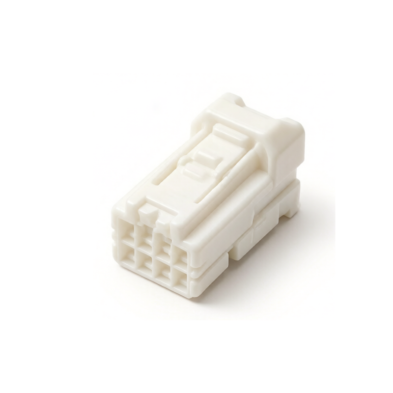
To many designers trained strictly on standard metric and imperial grids, 2.2mm appears highly unconventional. Yet, it exists to bridge a very specific engineering gap between extreme miniaturization and necessary current capacity. A 2.0mm system cannot safely handle the thermal dissipation required for a 4 Amp load. However, a 2.54mm setup violates the dimensional constraints of the enclosure. Here, 2.2mm provides a precise compromise. It offers slightly thicker contact terminals and increased dielectric spacing without adopting the full bulk of a standard 0.1 inch footprint.
This specific dimension is heavily localized within niche manufacturing ecosystems. It is highly prevalent in light electric vehicle architectures. A primary use case involves Battery Management Systems for E-bikes and electric scooters. Balancing wires require a plug compact enough to fit snugly against battery cells but rugged enough to handle moderate current spikes.
Specifically, engineers often rely on a 2.2mm pitch 8P male connector housings for these battery packs. An 8-pin configuration perfectly aligns with standard multi-cell monitoring circuits. It provides the exact dielectric clearance needed to prevent cross-talk between balancing wires while surviving continuous road vibration. Because it falls outside universal norms, procurement specialists must verify long-term component availability before locking this dimension into a new product lifecycle.
Equivalent to exactly 0.1 inches, the 2.54mm pitch is the undisputed historical and practical gold standard of electronic hardware. Its origins trace back to the early days of through-hole printed circuit boards. Components were placed on a strict grid. Today, it remains universally compatible with prototyping breadboards, perfboards, and standard pin headers. This universal standardization means hardware teams can prototype, test, and iterate rapidly without waiting weeks for custom assemblies.
The physical bulk of this standard provides substantial advantages for high-reliability designs. Electrically, the wider spacing easily accommodates 4 Amps to 5 Amps per pin. Specialized designs handle even more. The increased clearance permits higher voltage ratings before dielectric breakdown becomes a risk.
Mechanically, the wider spacing accommodates significantly thicker terminal pins. These are typically 0.64mm square posts. These rugged pins resist shear forces. They are much easier to hand-solder, blindly mate, or repair in the field. Furthermore, the wider spacing perfectly accommodates thicker wire gauges. It typically supports 22 to 28 gauge wires with ample room for thick insulation jackets.
Despite its proven reliability, avoid this size in ultra-compact consumer electronics or modern sensor enclosures. The cumulative footprint of a 20-pin 2.54mm header is massively larger than its 2.0mm counterpart. Forcing this standard into a tight build will invariably force designers to increase the overall size of the board and the final product enclosure.
The foremost factor driving your decision must be the electrical load. Evaluate both the continuous current and peak transient spikes of the circuit. Higher power requirements necessitate wider spacing. This allows for larger conductive terminals and better heat dissipation. Operating voltage is equally critical. High-voltage industrial designs must utilize wider gaps to meet safety standards for creepage and clearance. This prevents electrical arcing across the board surface.
The chosen dimension strictly dictates the maximum wire size that can be utilized. The physical constraints of the plastic cavity mean that larger wires simply will not fit into tightly spaced configurations. If power requirements dictate thick wire to minimize voltage drop, a 2.54mm spacing is usually mandatory. Forcing a wire gauge that is too large into a small cavity compromises the crimp integrity. It causes the insulation to splay and prevents the terminal from seating properly.
Industrial machinery subjects electronics to severe, continuous vibration. To prevent accidental disconnection, designs require positive locking latches, Terminal Position Assurance clips, and Connector Position Assurance locks. The selected spacing drastically impacts the bulkiness of these housings. A 2.54mm setup with full locking features consumes a massive amount of 3D space. If volume is limited, you may have to drop down to a 2.0mm equivalent to fit the locking housing into the enclosure. Ensure the electrical load allows for this downgrade.
Mating a small daughterboard to a larger motherboard in tight spaces requires careful height planning. Pitch influences not just the horizontal footprint, but also available low-profile options. Narrower gaps generally offer lower mating heights. This is critical when boards must be stacked closely together. However, tighter pin spacing requires finer trace widths and smaller vias. This increases the complexity and cost of bare board manufacturing.
When specifying wire-to-board connectors, strain relief becomes a primary concern. As spacing decreases, the individual wires exiting the rear of the housing are forced closer together. If the cable bundle bends, the lack of space causes insulation jackets to rub. It transfers mechanical strain directly to the fragile crimp joints. To mitigate this in high-density setups, engineers often must specify additional strain relief features like heat shrink tubing or overmolding. Tightly packed parallel wires over long distances can also introduce electromagnetic crosstalk. This necessitates careful signal-to-ground assignments.
Mating two rigid printed circuit boards introduces the challenge of mechanical tolerance stack-up. A 2.54mm spacing offers a forgiving tolerance window. The thicker pins guide themselves into receptacle chamfers even with slight misalignment. Smaller pitches require high-precision alignment. A misalignment of just a fraction of a millimeter on a 2.0mm rigid connection results in bent pins, stressed solder pads, or total mechanical failure during automated assembly.
A frequent scenario during prototyping involves connecting an off-the-shelf sensor module featuring a 2.0mm header to a legacy control board designed with 2.54mm receptacles. It is physically impossible to force a female plug of one size onto a male header of another. Doing so bends the pins outward. It ruins the contact plating and destroys retention force.
To bridge this gap reliably, engineers use custom-crimped cable assemblies featuring a 2.0mm housing on one end and a 2.54mm housing on the other. For rigid board-to-board adaptations, the best solution is designing a small interposer transition board. This simply routes traces from a 2.0mm footprint on the top layer to a 2.54mm footprint on the bottom.
Maintaining a low-profile design when forced to use standard 2.54mm components presents a strict height challenge. Standard vertical through-hole headers are often too tall for modern enclosures. Solutions include utilizing bottom-entry receptacles. The mating pins pass through routed slots in the board to connect from underneath. Another approach is using right-angle headers. These lay flat against the board, transforming vertical height limits into horizontal footprint requirements.
To facilitate rapid decision-making for procurement and design teams, the following matrix compares the three dimensions across critical engineering parameters.
Feature / Specification | 2.0mm Pitch | 2.2mm Pitch | 2.54mm Pitch |
|---|---|---|---|
Relative Footprint | Highly compact, low profile | Medium, non-standard compromise | Large, high clearance |
Typical Current Rating | 1.0A - 3.0A per pin | 2.0A - 4.0A per pin | 3.0A - 5.0A+ per pin |
Standard Wire Range | 24 to 30 Gauge | 22 to 28 Gauge | 20 to 28 Gauge (Thicker insulation) |
Mechanical Durability | Moderate (requires precise handling) | Good (balances size and strength) | Excellent (resists high vibration/shock) |
Ideal Applications | ADAS, IoT, infotainment, tight spaces | Battery systems, E-bikes, legacy standards | Power distribution, heavy industry, prototyping |
Availability & Sourcing | High (Industry standard for high-density) | Low (Specialized niche suppliers) | Very High (Universal standard) |
Choosing the right connector pitch is a delicate balancing act. You must weigh strict board space limitations against unwavering electrical needs and environmental stresses. Smaller configurations save crucial room but carry less current and require gentler handling. Standard larger sizes offer unmatched durability and power capacity for tough industrial jobs, but consume valuable real estate.
Always review your continuous current ratings, wire gauge requirements, and vibration limits before locking in a footprint. Selecting the best fit early in the design phase ensures long-term system reliability and prevents costly board revisions down the line. If you are navigating a complex build and need components that meet exact specifications, browse the extensive catalog at JinKeJi to find the perfect connection solution for your architecture.
No. Even for a simple 2-pin connection, the 0.54mm difference in spacing causes the pins to splay, bend, or fail to seat properly. You must always use matching sizes to ensure electrical continuity and prevent irreversible mechanical damage to the metal contacts.
While 2.54mm has historically been the standard for automotive power distribution, modern vehicle electronics are heavily shifting toward 2.0mm and even smaller geometries. This rapid shift is driven by the need to accommodate high-density infotainment systems and advanced sensor modules within limited dashboard space.
A larger center-to-center distance directly increases the overall width, length, and height of the plastic molding. If your application requires heavy-duty locking mechanisms or Terminal Position Assurance for vibration resistance, a 2.54mm housing consumes significantly more board area than a 2.0mm equivalent.
The 2.2mm dimension is considered non-standard in general global electronics. However, it is highly prevalent in very specific industrial sectors, such as battery management systems for electric scooters and certain legacy manufacturing ecosystems. Sourcing mating parts for this size requires careful supplier verification.
To measure pitch accurately, use digital calipers. Measure the distance from the exact center of one pin to the exact center of the adjacent pin. If the pins are too small, measure the total distance across multiple pins and divide by the number of gaps between them to get a precise average.
While possible for low-speed signals, 2.54mm is generally not recommended for modern high-speed data transmission like USB 3.0 or high-frequency video. The larger physical size and longer unshielded pin lengths introduce impedance mismatches and electromagnetic interference. For high-speed data, engineers use specialized, tightly spaced, impedance-controlled connectors.


