

Views: 0 Author: Site Editor Publish Time: 2026-07-30 Origin: Site


Designing modern electronics demands absolute precision in every component you select. You might optimize the primary silicon perfectly, but ignoring the physical interconnects risks immediate failure. The mechanical pathways linking your subsystems are just as critical as the microprocessors running them.
Selecting the wrong interconnect solution can lead to severe signal degradation, frustrating PCBA assembly bottlenecks, or catastrophic mechanical failure in the field. A simple mismatch in vibration tolerance cascades into major system redesigns and delayed product launches. This choice dictates device form factor, manufacturing scalability, and overall system reliability.
This guide evaluates mechanical constraints, electrical performance, and manufacturing realities. We will explore three vital interconnect categories to support your final component shortlisting. You will learn how to navigate tolerance stack-ups, manage signal integrity, and balance automated assembly requirements against physical spatial limits.
Board-to-Board Connectors maximize space efficiency and signal integrity but require strict manufacturing tolerances and rigid PCB alignment.
Wire-to-Board Connectors offer modularity and assembly flexibility, ideal for connecting independent sub-assemblies or external components to a central logic board.
Wire-to-Wire Connectors provide spatial freedom and external routing capabilities, often utilized for long-distance power distribution or harsh-environment external connections.
Selection Rule of Thumb: Design decisions should prioritize spatial constraints (Z-axis height), automated assembly compatibility (SMT/THT), and required mating cycles over unit cost alone.
These components facilitate the direct mating of two printed circuit boards without relying on cable intermediates. Hardware engineers generally deploy them in tightly packed enclosures where space remains at an absolute premium. They support multiple physical orientations depending on system architecture. Mezzanine configurations stack boards parallel to each other. Coplanar configurations link boards edge-to-edge. Orthogonal or perpendicular configurations join boards at right angles, typically seen in backplane designs.
The primary use case involves high-density, high-speed data transfer. Telecom servers, IoT gateways, and industrial programmable logic controllers rely heavily on Board-to-Board Connectors. They minimize the physical footprint while maintaining incredibly tight signal paths.
This architecture bridges a discrete wire or a multi-wire cable harness directly to a PCB. The system usually consists of two halves. A rigid header solders directly onto the circuit board. A wire-crimped receptacle housing then plugs into this header.
We often see Wire-to-Board Connectors utilized for dynamic power delivery or sensor routing. They connect external displays, batteries, or cooling fans to central motherboards. Systems requiring high modularity for field servicing depend on this architecture. It allows technicians to unplug a malfunctioning peripheral without desoldering components.
These components connect two wire-terminated cables together entirely outside of the PCB environment. They create a free-hanging joint floating within the enclosure or outside the device entirely.
Their primary use case involves extending cable reach across large physical spans. Automotive harnesses rely heavily on Wire-to-Wire Connectors to distribute power throughout a vehicle chassis. They also excel at passing connections through bulkheads or sealed enclosures. Manufacturers frequently specify them for harsh environments requiring robust IP-rated waterproofing and dust protection.
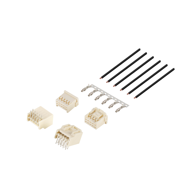
Pitch size determines the center-to-center distance between adjacent pins. Board-to-board solutions dominate the micro-pitch arena. You will frequently find them in 0.35mm to 1.0mm ranges. Their rigid mounting stability prevents tiny pins from bending during insertion.
Conversely, wire-to-board and wire-to-wire variants generally utilize much larger pitches. They typically range from 1.0mm up to 4.2mm or larger. They require this extra physical volume to accommodate thick wire insulation and complex internal crimping mechanics. A larger pitch provides the necessary room to isolate high-voltage lines safely.
Mechanical environments dictate interconnect survivability. Rigid B2B setups often rely on friction fit geometries or micro-locking tabs. They provide excellent holding force under static conditions. However, they remain highly vulnerable to mechanical stress if the primary PCBs flex or warp under thermal expansion.
Wire-based solutions prove highly resilient in intense, high-vibration environments. Connectors floating on a flexible cable harness inherently absorb shock. Manufacturers equip these housings with positive locking mechanisms. Features like Terminal Position Assurance (TPA) and Connector Position Assurance (CPA) physically lock the mating halves together. They prevent accidental disconnects during aggressive vibration profiles.
High-speed digital design demands short signal paths. Board-to-board setups provide the shortest possible physical route between active components. This minimizes impedance mismatches, crosstalk, and latency. They stand as the only viable choice for cutting-edge, high-speed protocols like PCIe Gen 5 or PAM4 signaling.
Cable-based routing introduces longer physical distances. This naturally elevates electromagnetic interference (EMI) risks. W2B and W2W setups excel at brute power transmission or low-speed analog signal routing. If you must send high-speed data over a cable, you must deploy heavily shielded cables and specialized impedance-matched connector housings.
Rigid connectors introduce immense alignment challenges during PCBA manufacturing. Evaluating the rigid constraints of a B2B setup requires careful mechanical modeling. Mating multiple discrete connectors between two rigid boards creates severe tolerance alignment risks. If the pin arrays misalign by fractions of a millimeter, the insertion force spikes. This shatters the plastic housing or rips solder pads directly off the FR4 substrate.
Wire-to-board assemblies completely eliminate this geometric hazard. The inherent flexibility of the cable harness forgives broad tolerance mismatches. Technicians easily guide the receptacle into the header regardless of minor chassis variations.
Assessing thermal profiles is mandatory before finalizing the Bill of Materials. Surface Mount Technology (SMT) headers require precise reflow compatibility. Engineers must ensure the plastic resins withstand oven temperatures without blistering. SMT dominates high-density logic boards.
Through-Hole Technology (THT) offers vastly superior mechanical retention. High-insertion-force wire harnesses apply massive leverage against the PCB header during extraction. THT pins physically anchor deep into the board substrate, preventing technicians from accidentally tearing the header away during routine maintenance.
Sometimes you must evaluate the direct-solder alternative. You can bypass the header entirely using "Board-in" terminals. In this scenario, automated machines crimp special terminals onto bare wires. Factory workers then solder these terminals directly into the PCB via through-holes.
This strategy solves extreme Z-axis space constraints. It also removes the cost of a mating header component. However, the trade-off in reworkability is massive. You permanently tether the cable to the logic board. Field repairs require complete board replacement rather than a simple harness swap.
Use the framework below to benchmark your architectural options. We structure this comparison around real-world deployment parameters.
Interconnect Evaluation Matrix
Evaluation Criteria | Board-to-Board (B2B) | Wire-to-Board (W2B) | Wire-to-Wire (W2W) |
|---|---|---|---|
Space & Form Factor | Wins heavily on overall volumetric reduction. Ideal for ultra-thin wearables. | Wins on flexible spatial routing around bulky internal components. | Occupies the most space but frees up valuable PCB real estate. |
Assembly & Modularity | Requires precise, automated pick-and-place machinery. | Allows separate sub-assembly manufacturing. Fast plug-and-play installation. | Highly modular. Harnesses are built off-site and clipped together instantly. |
Field Servicing & Maintenance | Often requires disassembling the entire hardware stack to access. | Facilitates easy, modular component swapping by field technicians. | Provides the easiest maintenance access. Allows inline testing. |
Environmental Resilience | Typically remains safely inside the primary device enclosure. | Moderately protected depending on enclosure sealing. | Provides the easiest path to true IP67/IP68 waterproof overmolding. |
Before releasing your final schematic, run your chosen components through this mitigation checklist. Overlooking these variables often results in late-stage prototype failures.
Assess Mating Cycles: Verify the manufacturer's rated mating cycles on the datasheet. Standard tin-plated contacts oxidize quickly and only survive 20 to 50 insertions. Frequent testing or peripheral swapping requires robust gold-plated contacts to prevent fretting corrosion.
Verify Current Derating: Never assume maximum current applies to all pins simultaneously. Cross-reference the American Wire Gauge (AWG) with ambient temperature curves and circuit density. Grouping too many power lines together causes localized thermal runaway. This step proves crucial for high-power W2B or W2W applications.
Regulatory & Compliance Verification: Ensure chosen connector families meet necessary environmental and safety standards. Confirm UL flammability ratings, such as UL94V-0, to prevent catastrophic fire spread. Always verify current RoHS compliance for global market distribution.
Next Steps: Do not rely purely on digital specs. Advise your mechanical engineers to request 3D CAD models. Verify the exact PCB footprint alignment. Order physical component samples for real-world insertion and extraction force testing before locking the final BOM.
System architects must acknowledge there is no universal "best" interconnect. Success lies in choosing the right architecture for a specific mechanical envelope and a specific manufacturing process. Relying blindly on legacy components invites systemic reliability issues.
We encourage engineering teams to finalize their spatial layouts and thermal constraints before committing to a specific family. Mapping out the physical routing paths early prevents desperate, last-minute redesigns. Rigorous mechanical testing will validate your assumptions and expose hidden assembly friction.
Take action today by consulting with a dedicated connector specialist. Download the latest product specification datasheets and review the precise current derating curves. Request physical engineering samples immediately. Hands-on testing remains the ultimate validation method for any application.
A: Yes. Utilizing board-in crimps or manual soldering saves physical board space. It also removes the housing component entirely. However, this method drastically increases manual assembly time during production. Furthermore, it completely eliminates field repairability. Technicians cannot easily un-solder multi-wire harnesses on-site.
A: Blind mating involves plugging halves together without visual alignment. Technicians common perform this in deep drawer or server chassis applications. It requires specialized guide pins, heavy-duty lead-in chamfers, and self-aligning shrouds. These robust housings physically shift to correct minor misalignments, preventing fragile internal pin damage.
A: Smaller pitch leaves significantly less room for thick metal terminals and large AWG wire insulation. This physical limitation generally caps micro-pitch B2B or W2B connectors at low amperages, usually between 1 to 3 amps. Conversely, larger pitch designs exceeding 3.0mm can comfortably handle 5 to 10 amps.

![[GT8E-10S-HU] 2.0 Pitch 10P Plastic Housing](http://iororwxhimpllk5p-static.micyjz.com/cloud/ljBpkKlmliSRollpqnnrkp/26-GT8E-10S-HU-640-640.png "[GT8E-10S-HU] 2.0 Pitch 10P Plastic Housing")
![[ZE05-4S-HU/R] 2.0pitch 4P Spacing Connector Assembly](http://iororwxhimpllk5p-static.micyjz.com/cloud/llBpkKlmliSRollpqnoikp/24-ZE05-4S-HU-R-640-640.jpg "[ZE05-4S-HU/R] 2.0pitch 4P Spacing Connector Assembly")
![[ZE05-16DS-HU/R] 2.0pitch 16P Spacing Connector Assembly](http://iororwxhimpllk5p-static.micyjz.com/cloud/lnBpkKlmliSRollpqnojkp/23-ZE05-16DS-HUR-640-640.png "[ZE05-16DS-HU/R] 2.0pitch 16P Spacing Connector Assembly")
![[174928-1] 3.5 Pitch, 3P White Housing](http://iororwxhimpllk5p-static.micyjz.com/cloud/lrBpkKlmliSRollpqnrkkp/22-640-640.jpg "[174928-1] 3.5 Pitch, 3P White Housing")
