

Views: 0 Author: Site Editor Publish Time: 2026-10-05 Origin: Site


Have you ever ordered parts, only to find they refuse to mate on the assembly line? Mismatched components are a notorious source of production delays. They waste engineering budgets and often lead to costly electrical shorts in the field. Building a reliable electronic device demands a holistic approach to component selection. A successful connection functions as a unified ecosystem, rather than a random collection of isolated parts.
In this guide, you will learn the exact mechanical and electrical parameters required to match your interconnects perfectly. By understanding the intricate relationship between the plastic shell, the metal contacts, and the board-mounted pins, you can eliminate procurement errors and ensure long-term structural integrity.
Key Takeaways
Always match the exact pitch size, the measured distance between pins, across all three mating components.
Ensure the metal contacts accommodate your specific wire gauge and insulation diameter to fit securely inside the plastic shell.
Never mix contact plating materials—such as mating gold with tin—to prevent destructive galvanic corrosion.
Verify electrical ratings across the entire wire-to-board connectors assembly, as the weakest link dictates your maximum capacity.
Stick to the same manufacturer and product series for guaranteed mechanical and electrical compatibility.
To ensure long-term reliability, engineers must first understand the distinct functions of the three main pillars of a connection system. Each piece plays a non-negotiable role in maintaining power delivery and signal integrity. When one part fails, the entire system goes down.
These are the insulating plastic shells that form the outer structure of the connection. Typically manufactured from durable thermoplastics like Nylon 66 or PBT, these shells serve multiple critical functions. They physically protect the delicate metal contacts from environmental damage, dust, and physical stress. Specifically, they provide the necessary locking mechanisms to keep the connection secure under heavy vibration. Their internal geometries are molded precisely to ensure correct polarity and exact pin alignment.
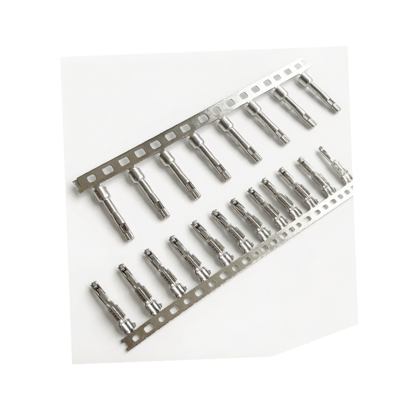
These highly conductive metal contacts are mechanically crimped onto the stripped ends of a wire. Usually stamped from materials like brass, phosphor bronze, or beryllium copper, they act as the actual conduits for electrical current. Their primary role is to carry power or data efficiently. Once crimped, they lock securely into the internal cavities of the plastic housing via small metal tangs or retention lances.
These are rigid, board-mounted components consisting of male metal pins encased in a plastic base. Soldered directly to the printed circuit board, they act as the stationary mating base for the plug assembly. The manufacturing of these components requires strict tolerances to ensure flawless mating. To better grasp the exact engineering required to produce these parts, you can explore how PCB headers are manufactured using precision interconnect processes.
In the realm of electronic design, pitch is the absolute most critical dimensional specification. Pitch refers to the exact center-to-center distance between two adjacent pins. If the pitch does not match perfectly across your ecosystem, the components will simply never fit together.
Currently, the global electronics manufacturing sector is undergoing a massive shift toward high-density interconnects. Driven by the demands of smart automotive systems, compact IoT hardware, and wearable tech, engineers are moving away from bulky legacy standards. We see a sharp industry-wide transition toward micro-pitch solutions. While older systems relied on the robust 2.54mm standard, modern designs frequently push toward 1.25mm or even 1.00mm pitches. This evolution makes thermal derating calculations and strict dimensional adherence more critical than ever before.
The pitch size acts as an absolute physical constraint. A 2.54mm plastic shell will physically never mate with a 2.0mm header. Even a fraction of a millimeter difference causes the plastic to collide with the metal pins. This bends the contacts or breaks the board mount entirely. Furthermore, the pitch size directly limits the physical dimensions of the metal contacts you can utilize. A micro-pitch housing requires ultra-miniature contacts, which subsequently restricts the maximum wire thickness that can be safely crimped.
The relationship between the metal terminal and the plastic shell is where most procurement errors actually occur. Successfully matching these components requires strict adherence to wire specifications and physical dimensions. You cannot simply guess; you must verify the numbers.
Every crimp terminals design is engineered to accept a very specific range of American Wire Gauge sizes. Consider the ZE05-2022SCF series. This specific terminal features a 2.0mm pitch design tailored for 4 to 16-pin configurations. If a technician attempts to terminate a thicker wire than its designated rating into this contact, the metal wings will not fold correctly. This leads to exposed copper strands and a weak mechanical hold. By contrast, using a wire that is too thin results in a loose crimp. The wire will eventually slip out under tension, creating a dangerous high-resistance fault.
While the wire gauge dictates the thickness of the copper conductor, the insulation outer diameter dictates the thickness of the wire's plastic jacket. Many engineers overlook this simple metric. However, it is a critical failure point. A metal contact features two crimping zones: the conductor crimp for the bare wire, and the insulation crimp for strain relief. If the wire's jacket is too thick, the crimped metal becomes bulky. Consequently, it will physically fail to slide into the narrow cavities of the plastic shell.
Mechanical compatibility between mating components forms the foundation of structural integrity in any electronic assembly. Engineers must evaluate physical tolerances meticulously. This ensures the plug securely fits the receptacle under operational stress. Matching connector housings to their corresponding board mounts goes beyond merely aligning the pins. It requires a comprehensive understanding of locking mechanics, spatial orientation, and board mounting configurations.
To prevent costly rework, use this standard engineering verification table when cross-referencing your datasheets:
Mating Parameter | Verification Target | Failure Consequence |
|---|---|---|
Pitch Size | Exact center-to-center distance match | Physical collision, broken pins |
Wire Gauge | Fits terminal crimp barrel limits | High resistance, wire pull-out |
Insulation Outer Diameter | Fits inside plastic housing cavity | Jammed assembly, exposed copper |
Plating Material | Same metal on plug and receptacle | Galvanic corrosion, signal loss |
Vibration, thermal expansion, and mechanical shock cause improperly secured components to disconnect over time. To mitigate this risk, manufacturers design specific mating retention systems. A friction fit relies entirely on the tight dimensional tolerance between the plastic and the metal pins. This makes it suitable only for static environments. Positive locks, on the other hand, utilize a physical latch that engages with a window on the board mount. When pushing the plug into the receptacle, you should feel distinct tactile feedback—a firm click—confirming the lock is fully engaged.
Plugging a connector in backward reverses the electrical polarity. This mistake can instantly destroy sensitive chips on a circuit board. Polarization solves this hazard entirely. These features are physical asymmetries, such as molded ribs on the exterior of the shell that slide into dedicated grooves on the header wall. If an operator attempts to mate differently keyed components, physical interference halts the insertion immediately.
System integrity relies heavily on matching physical parts with exact electrical parameters. A successful connection requires that the electrical ratings of all components remain aligned. This ensures the system operates safely within its designated thermal and dielectric limits.
Every component in a connection ecosystem possesses a maximum current rating. When current flows through metal contacts, electrical resistance generates heat. Engineers must recognize that the smallest rating within the trio dictates the maximum safe current for the entire assembly. For example, if a board mount handles 5 Amps, but the wire contact only handles 3 Amps due to a thinner metal profile, your system capacity is strictly 3 Amps. Exceeding this limit causes localized overheating and will eventually melt the surrounding plastic.
Voltage ratings are primarily determined by the spatial separation between conductive elements and the insulating properties of the plastic. The pitch size dictates the clearance, which is the shortest distance through the air between two conductive parts. Meanwhile, the plastic material determines the creepage distance. If the applied voltage exceeds the dielectric withstanding capacity of the plastic, electrical arcing occurs between adjacent pins. This leads to catastrophic short circuits.
A pervasive issue in electronic procurement is the failure to match material science parameters. Mating incompatible contact platings is a primary cause of long-term device failure. These failures often manifest months after the product has been deployed in the field, leading to expensive product recalls.
Contact plating protects the base metal from oxidation while maintaining low electrical resistance. Tin plating is highly cost-effective and performs exceptionally well in static, high-normal-force applications. However, tin forms a hard oxide layer upon exposure to air, requiring a high mating force to wipe away during insertion. Gold plating does not oxidize. It offers exceptional conductivity, requires significantly less mating force, and withstands thousands of mating cycles without degrading. This makes gold ideal for low-voltage signal transmission.
The golden rule of tribology in electronics is simple: never mix dissimilar metals. Mating a gold-plated board pin with a tin-plated wire contact initiates a destructive process known as galvanic corrosion. Because gold and tin occupy different positions on the galvanic series, introducing ambient moisture creates a microscopic battery cell. The tin acts as an anode and rapidly corrodes. In addition, microscopic vibrations caused by thermal expansion lead to fretting wear. The harder tin oxide debris aggressively abrades the softer gold plating, resulting in a massive spike in contact resistance and eventual system failure.
Even experienced procurement specialists encounter severe assembly issues if they overlook the nuanced specifications defining mating parts. Avoiding these common engineering pitfalls is essential for maintaining production efficiency and brand reputation.
A frequent error is attempting to use a metal contact from one manufacturer inside a plastic shell from another. Many assume that identical pitch sizes guarantee compatibility. This is false. Even if a 2.54mm contact physically fits into a 2.54mm shell, the internal locking lances, retention tangs, and seating depths are highly proprietary. Mixing series compromises the retention force, causing the wire to push out when mated with the board. Always strictly adhere to the manufacturer's specified mating parts.
The mechanical integrity of a crimp relies on applying precise pressure. The tool must deform the metal barrel around the wire strands without severing them. Using generic pliers or an incompatible die set creates a deformed profile. If the insulation barrel is crimped too wide, it exceeds the internal cavity dimensions of the plastic, making insertion impossible. If crimped too loosely, the wire detaches under minimal tension.
To streamline the procurement process and eliminate compatibility errors, engineers should follow a rigorous methodology. When specifying interconnects for industrial or consumer applications, ensure all mechanical and electrical parameters align perfectly by verifying these exact steps:
Determine Electrical Needs: Begin by calculating the maximum voltage and continuous current the circuit requires. Identify the specific wire gauge needed to carry this current safely without exceeding thermal limits.
Select the Pitch and Space: Evaluate your available board real estate. Decide between standard pitches for robust power applications or micro-pitches for compact devices. Ensure the pitch provides adequate dielectric clearance.
Choose the Board Mount: Based on the manufacturing process, select between Surface Mount and Through-Hole styles. Determine if the cable routing requires a vertical or right-angle orientation, and verify the contact plating.
Match the Mating Parts: Consult the exact manufacturer datasheet for your chosen header. Identify the specific series and part numbers listed under compatible mates. Order the exact corresponding shells and contacts, ensuring the platings match perfectly.
Matching components correctly ensures your electronic devices operate safely under real-world conditions. Always verify the pitch size, electrical ratings, and insulation tolerances before you purchase any parts. Careful upfront planning prevents costly production delays, eliminates the risk of galvanic corrosion, and ultimately protects your product quality.
Generally, no. Even if the pitch size is identical, the internal locking lances, retention tangs, and specific dimensional tolerances vary significantly by manufacturer. Using incompatible parts compromises the mechanical retention force, leading to wires pulling out under tension. Always use the exact part number specified on the official datasheet to guarantee structural integrity.
You must check the manufacturer's technical datasheet for the specific part. The documentation explicitly lists the acceptable conductor size range, such as 22 to 26 AWG, and the maximum allowable insulation outer diameter. Exceeding the outer diameter prevents the crimped metal from fitting into the cavity, while using a wire too thin results in a loose, high-resistance connection.
Crimping a wire that is too large for the terminal will cause the metal wings to splay outward, making it impossible to insert into the plastic housing. Conversely, crimping a wire that is too small fails to create a gas-tight seal. This allows moisture to enter the joint, leading to oxidation, increased electrical resistance, and eventual thermal failure.
To measure pitch accurately, use digital calipers. Measure the distance from the exact center of one pin to the exact center of the adjacent pin. For higher accuracy on micro-pitch connectors, measure across multiple pins—for instance, across 10 spaces—and divide the total distance by 10 to find the precise average pitch.
Wire-to-board systems are designed to mate a suspended wire harness directly to a rigid header that is permanently soldered to a printed circuit board. In contrast, wire-to-wire systems are used to connect two free-hanging wire harnesses together in mid-air, utilizing a plug on one side and a receptacle on the other.
You must use a manufacturer-specific pin extraction tool. This specialized instrument slides into the front of the cavity to depress the metal locking tang. Once the tang is flattened, the wire slides smoothly out of the back of the plastic without causing permanent damage to the internal retention mechanisms. Never use excessive force or improper tools, as this destroys the component.
Ready to eliminate assembly errors and secure your supply chain? Whether you need robust power headers or ultra-compact micro-pitch solutions, selecting the right engineering partner is crucial. Explore the full range of precision-matched components and technical resources at Jinkeji to find the exact specifications for your next project.


