

Views: 0 Author: Site Editor Publish Time: 2026-08-03 Origin: Site


Modern vehicles rely heavily on complex electronic architectures. You must ensure robust connections between sensors, control units, and power systems. Selecting the wrong component often leads to parasitic resistance, signal degradation, or catastrophic field failures. These failures happen due to harsh operational environments. Engineers and procurement managers cannot afford to rely solely on basic pin counts. The stakes are simply too high for guesswork. You need a strict, evidence-based evaluation framework for specifying Automotive Connectors. This framework must balance electrical integrity, mechanical survivability, and regulatory compliance perfectly. Doing so prevents over-engineering while guaranteeing absolute reliability. In this guide, you will learn how to map electrical requirements accurately. We will explore application zoning in detail. You will navigate rigorous industry standards and learn to mitigate assembly risks effectively. By the end, you will confidently select the ideal interconnect solutions for any modern vehicle platform.
Automotive connectors must be evaluated across three uncompromising dimensions: electrical capacity, environmental sealing (IP rating), and mechanical durability (vibration/mating cycles).
Application zoning (e.g., cabin vs. under-hood vs. chassis) dictates baseline material and testing requirements.
Compliance with industry standards (USCAR-2, LV214) is non-negotiable for supply chain integration and liability mitigation.
Total cost goes beyond unit price; factoring in installation tooling, validation testing, and failure rates is critical for final selection.
We need a robust decision matrix to choose components confidently. Let us break down the evaluation process into three foundational pillars. Establishing these strict criteria upfront eliminates unsuitable parts early in the design cycle.
Mapping current rating (amps) and operating voltage forms your baseline. You must match the component's rating to the circuit's absolute maximum load. Thermal derating plays a huge role in this process. As ambient temperature rises, a component's current-carrying capacity drops significantly. A terminal rated for 15 amps at 20°C might safely carry only 8 amps at 105°C. Always consult thermal derating curves before finalizing a wire harness design. Ignoring this step invites dangerous localized heating.
Different vehicle systems demand entirely different electrical traits. High-power delivery systems require massive current handling capabilities. Modern EV powertrains often push hundreds of amps continuously. Conversely, low-voltage systems focus heavily on high-frequency data transmission. Components used in CAN bus networks, LiDAR sensors, and autonomous driving modules fall into this category. They need exceptional signal integrity to prevent data packet loss. You must ensure proper impedance matching for these delicate, high-speed communication lines.
Automotive environments are incredibly hostile. You must understand Ingress Protection (IP) ratings in an automotive context to ensure survival. An IP67 rating ensures the connection survives temporary water submersion. An IP69K rating guarantees protection against high-pressure, high-temperature washdowns. Selecting the correct IP rating prevents internal corrosion.
Chemical resistance is equally vital for vehicle longevity. Plugs often face direct exposure to engine oil, ethylene glycol coolant, brake fluid, and corrosive road salt. Plastic housings must not swell, crack, or become brittle when exposed. Operating temperature ranges also dictate your material choices strictly. A standard range spans from -40°C up to +125°C. However, components near exhaust manifolds or engine blocks often require specialized high-temp materials rated up to +150°C.
Constant vibration literally shakes electrical connections apart over time. You must account for vibration severity profiles based on specific mounting locations. Engine-mounted components face extreme, high-frequency harmonic vibrations. Body-mounted modules experience lower-frequency, structural road impacts. Thermal cycling also causes materials to expand and contract, loosening internal pins over years of service.
Terminal retention force ensures individual wires stay securely pinned inside the housing. You should rely on specific mechanical locking mechanisms to ensure stability. Connector Position Assurance (CPA) guarantees the two housing halves are fully mated and locked. Terminal Position Assurance (TPA) ensures individual wire pins are fully seated inside the housing body. These redundant safety features prevent accidental unmating during harsh vehicle operation.
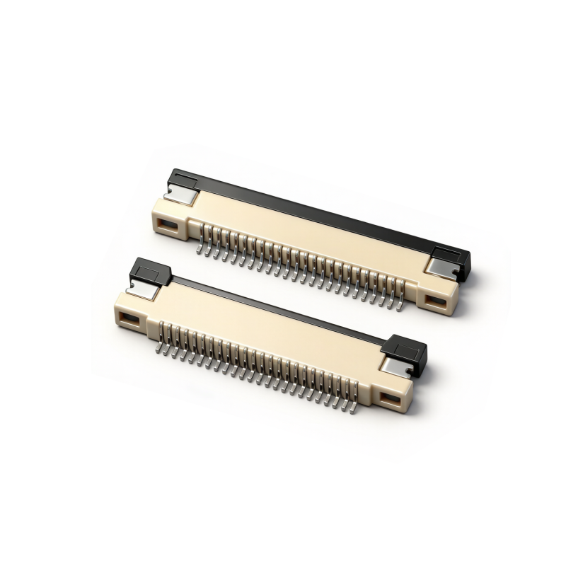
Categorizing parts by their physical location helps buyers shortlist solutions rapidly. The vehicle layout dictates environmental stresses entirely. Let us look at the three primary application zones.
The engine bay presents the toughest engineering challenge. This zone requires sealed, high-temperature, heavy-duty Automotive Connectors. You will typically specify sealed rectangular housings or heavy-duty circular types here. They must withstand extreme vibration profiles and relentless chemical exposure. Hot engine oils and coolants can quickly degrade inferior plastics. Proper silicone sealing glands and rugged external latches are absolutely mandatory to maintain circuit integrity.
Passenger compartments offer a much safer, climate-controlled environment. Here, the engineering focus shifts toward miniaturization and high-density pin counts. High-speed data transmission takes priority over heavy current handling. You will often specify FAKRA or High-Speed Data (HSD) interfaces for infotainment displays, dashboard cameras, and telematics units.
Because the cabin remains dry, unsealed components are frequently acceptable. Dropping the heavy silicone sealing requirements reduces the physical footprint significantly. It also lowers the individual unit price. This makes high-volume harness production much more efficient for interior routing.
Electric vehicles introduce highly specialized safety requirements. The main powertrain operates at 400V, 800V, or even higher. These systems require robust electromagnetic shielding to prevent interference with nearby low-voltage sensors. Touch-safe designs are non-negotiable. They protect assembly technicians and mechanics from accidental shocks during maintenance. Furthermore, you must integrate High-Voltage Interlock Loop (HVIL) safety mechanisms. The HVIL circuit acts as an internal safety net. It instantly cuts high-voltage power if a housing is physically disconnected.
Application Zone | Primary Engineering Challenges | Typical Sealing Requirement | Key Focus Areas |
|---|---|---|---|
Under-Hood / Engine Bay | High heat, extreme vibration, caustic chemicals | IP67, IP69K (Fully Sealed) | Vibration resistance, TPA/CPA, material durability |
Cabin / Infotainment | Space constraints, fast data speeds | Unsealed (IP20) | Miniaturization, high-speed signal integrity |
EV High-Voltage Powertrain | High voltage, EMI, critical safety risks | Sealed + Heavily Shielded | HVIL integration, touch-safe design, thermal management |
You must rely on rigorous testing to validate any component before procurement. Demonstrating strict compliance ensures passenger safety and mitigates corporate liability. Never assume a component is suitable without checking its certification background.
In North America, engineers rely heavily on the USCAR-2 standard. It outlines rigorous performance testing for automotive electrical terminals and plastic housings. This standard simulates decades of road abuse in mere weeks. In Europe, the LV214 standard dictates similar, highly detailed testing protocols for motor vehicle contacts. German automakers originally developed LV214. Today, it serves as a global benchmark for terminal crimp validation. Adhering to these frameworks is practically mandatory for global supply chain integration.
You cannot ignore material safety directives during selection. RoHS (Restriction of Hazardous Substances) and REACH compliance are crucial. They govern the use of hazardous chemicals and heavy metals in manufacturing processes. Compliant parts guarantee seamless entry into strict international markets.
Never take a simple datasheet at face value. We advise readers to request comprehensive OEM test data. Reviewing these reports verifies the manufacturer's claims and builds engineering confidence. Look for detailed reports covering:
Thermal shock testing to simulate rapid, extreme temperature fluctuations.
Mechanical drop testing to ensure structural housing integrity upon impact.
Accelerated aging tests to predict long-term plastic and rubber degradation.
By requesting these documents, you can specify reliable Automotive Connectors that already possess pre-certified test documentation.
Designing a perfect circuit on paper is only half the battle. You must address operational realities to prevent manufacturing bottlenecks. Overlooking the assembly process leads to severe production delays.
Always evaluate your tooling ecosystem early. Does the new component require proprietary, expensive crimping tools? Ideally, new components should fit seamlessly within existing wire harness assembly lines. Standardized terminals prevent production delays. They reduce training burdens on factory floors. Consistent crimp quality guarantees long-term electrical reliability. Poor crimps cause localized heating and eventual circuit failure.
Human error during factory assembly causes countless field failures. You must prioritize Poka-Yoke, or mistake-proofing, in your design phase. Look for robust keying options on the housings. Physical keys prevent mismatched plugs from mating entirely. Color-coding provides a clear visual cue to assembly workers. These simple ergonomic features stop cross-mating completely, protecting sensitive electronics from reverse polarity.
Wires constantly bend and pull during vehicle operation. You must discuss the necessity of proper strain relief. Integrating backshells protects the exposed wire entry points from stress. Using designated cable tie-down points prevents wire chafing against sharp metal chassis edges. Without strain relief, mechanical tension leads directly to terminal pull-out. This causes intermittent electrical faults that are notoriously difficult for mechanics to diagnose.
Choosing the right supplier is just as important as choosing the right part. Here is how you can finalize your selection with absolute confidence.
A brilliant component is useless if it arrives late. You must evaluate vendor lead times carefully. Assess their global availability and logistics networks. Does the vendor offer second-source potential? Having a backup manufacturing location prevents production bottlenecks if a specific factory goes offline unexpectedly.
Do not rush into massive bulk orders. We highly recommend requesting engineering samples first. Physical fit-checks are invaluable during development. Conduct in-house validation tests to confirm how the housings mate in tight physical spaces. Hands-on prototyping often reveals minor ergonomic issues earlier in the cycle. Fixing issues during the prototype phase saves vast amounts of engineering effort.
Bring your harness design specs directly to vendor application engineers. Do this as early as possible in the design cycle. Application engineers understand their catalog intimately. They can recommend specialized Automotive Connectors that perfectly match your exact routing, power, and data constraints. Using their expertise streamlines your final selection process.
Verify global lead times and identify primary factory locations.
Request physical engineering samples for hands-on fit-checks.
Perform internal mating tests and mock harness routing exercises.
Consult vendor engineers with preliminary CAD models to confirm fitment.
Finalize the bill of materials (BOM) based on confirmed market availability.
Choosing the best interconnect solution is a delicate balancing act. You must weigh harsh environmental demands against precise electrical specifications and strict assembly realities. Striking this precise balance ensures reliable vehicle operation for years. Remember, over-specifying wastes valuable engineering budgets on unnecessary ruggedness. Conversely, under-specifying invites catastrophic system failures on the road.
Take a proactive approach to your next vehicle design cycle. Reach out to technical sales teams early in the process. Download full specification sheets and review the thermal derating curves thoroughly. Finally, request a sample kit. Testing physical prototypes against your specific wire harness constraints remains the best way to guarantee lasting engineering success.
A: Sealed types feature internal rubber gaskets and individual wire seals, achieving IP67 or IP69K ratings. They block water, dust, and aggressive chemicals, making them ideal for exterior and engine bay use. Unsealed variants lack these gaskets, typically carrying an IP20 rating. They are lighter, smaller, and less expensive, perfect for dry, climate-controlled cabin interiors.
A: CPA stands for Connector Position Assurance. It is a secondary locking latch ensuring the two main housing halves remain securely mated. TPA means Terminal Position Assurance. It is an internal plastic insert that guarantees individual wire pins are fully seated inside the housing, preventing them from backing out under severe vibration.
A: Yes. EV powertrains operate at extremely high voltages and currents. They require heavy-duty shielding to block electromagnetic interference (EMI). Additionally, EV connectors feature High-Voltage Interlock Loop (HVIL) safety circuits. They utilize specific touch-safe geometries to protect maintenance personnel from accidental electrocution during servicing.
A: As a general rule, use gold plating for low-current, high-speed data transmission, or high-vibration areas. Gold resists oxidation and fretting corrosion perfectly. Use tin plating for static, higher-current power applications. Tin is cost-effective but susceptible to fretting corrosion if exposed to continuous micro-vibrations without adequate contact pressure.


